Smoothing the Output of a Full-Wave Bridge Rectifier
In our previous post, we discussed how a Full-Wave Bridge Rectifier flips the negative side of an AC signal to positive. While this is a huge step forward, the output is still what we call “pulsating DC”. The voltage drops to zero 100 or 120 times a second (depending on your mains frequency).
If you try to power an Arduino or an audio amplifier with pulsating DC, your microcontroller will reset constantly, and your speakers will hum loudly.
To fix this, we need to fill in the gaps. We need a Smoothing Capacitor.
The Solution: The “Water Tank” Analogy
Think of the Bridge Rectifier as a water pump that pumps in spurts. It provides water, but the flow stops for a split second between pumps.
A Smoothing Capacitor acts like a water tank placed after the pump:
When the pump pushes water (voltage rises), it fills the tank (charges the capacitor) and powers the house (the load).
When the pump stops for a moment (voltage drops to zero), the tank releases its stored water to keep the flow steady.
In electronics, the capacitor stores electrons during the peak voltage and releases them when the voltage drops, creating a much smoother line.
The Circuit Diagram: Adding the Capacitor
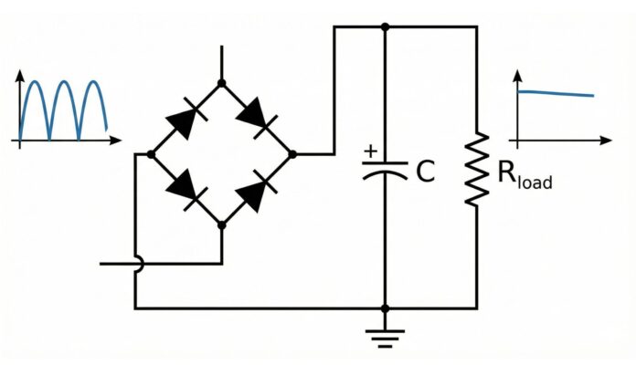
To implement this, you place a capacitor in parallel with your load resistor. Here is the updated circuit topology:
How to Build It
Looking at the diagram above, here is the setup:
The Rectifier: The four diodes (D1 to D4) are arranged in the standard bridge configuration.
The Capacitor (C): This is connected across the output terminals. Note: We usually use electrolytic capacitors for this task because they have high capacitance. These are polarized, meaning they have a positive (+) and negative (−) side. You must connect the positive leg to the positive output of the bridge.
The Load: Your device (represented by the resistor) is connected in parallel with the capacitor.
Choosing the Right Capacitor
Two main values matter when selecting your smoothing capacitor:
1. Capacitance (Farads)
Measured in microfarads (µF). The higher the value, the better the smoothing.
Too low: You will still have “ripple” (a slight waviness in the voltage).
Rule of Thumb: For basic low-power circuits, a 470µF or 1000µF capacitor is a great starting point.
2. Voltage Rating
This is the maximum voltage the capacitor can handle before it fails (sometimes violently).
The Rule: The rating must be higher than the peak voltage of your AC input.
Safety Margin: Always choose a capacitor rated for at least 25–50% more than your expected voltage. If your circuit outputs 12V, use a 25V capacitor.
What Comes Next?
Congratulations! You now have a functional DC power supply. However, the voltage might still fluctuate slightly depending on how much current your load draws.
To make this a “lab-grade” power supply perfect for sensitive microcontrollers, the final step is usually adding a Voltage Regulator (like the LM7805) after the capacitor to lock the voltage at a precise level.
Summary Checklist
☐ Connect the capacitor in parallel with the output.
☐ Watch the polarity (negative stripe goes to ground).
☐ Ensure the voltage rating is higher than your peak input.